In recent years design certification has emerged as the preferred way for clients to provide evidence equipment complies with a specific Australian Standard. At Dynamic Engineering we make achieving compliance as easy as possible for our clients by providing a design certification service. We specialise in Civil/Structural Design, Maintenance Tools and Lifting Equipment Design Certification. Additionally, the WA Department of Mines, has released some information, relating to industry regulation and safety. Whether it is a new design or looking at improving an existing one, we can assist you every step of the way. Our flexible approach also means that no assignment is too small.
Design Certification
There are two main ways to accomplish certification:
- 3rd party design calculations in accordance with the Australian Standard, combined with quality control during fabrication (MDR)
- Physical testing of equipment.
Third party design Calculations
We use the relevant Australian Standards (for example AS 3990) to analyse structures, equipment or machinery to ensure design compliance. After this analysis, we summarise these calculations in a design report.
Finite Element Analysis
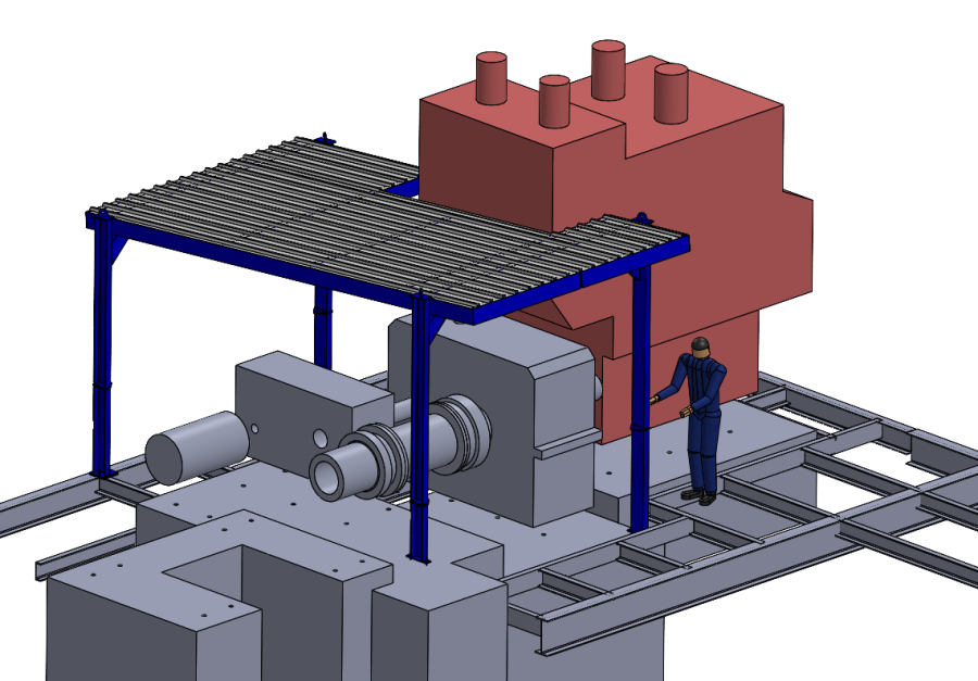
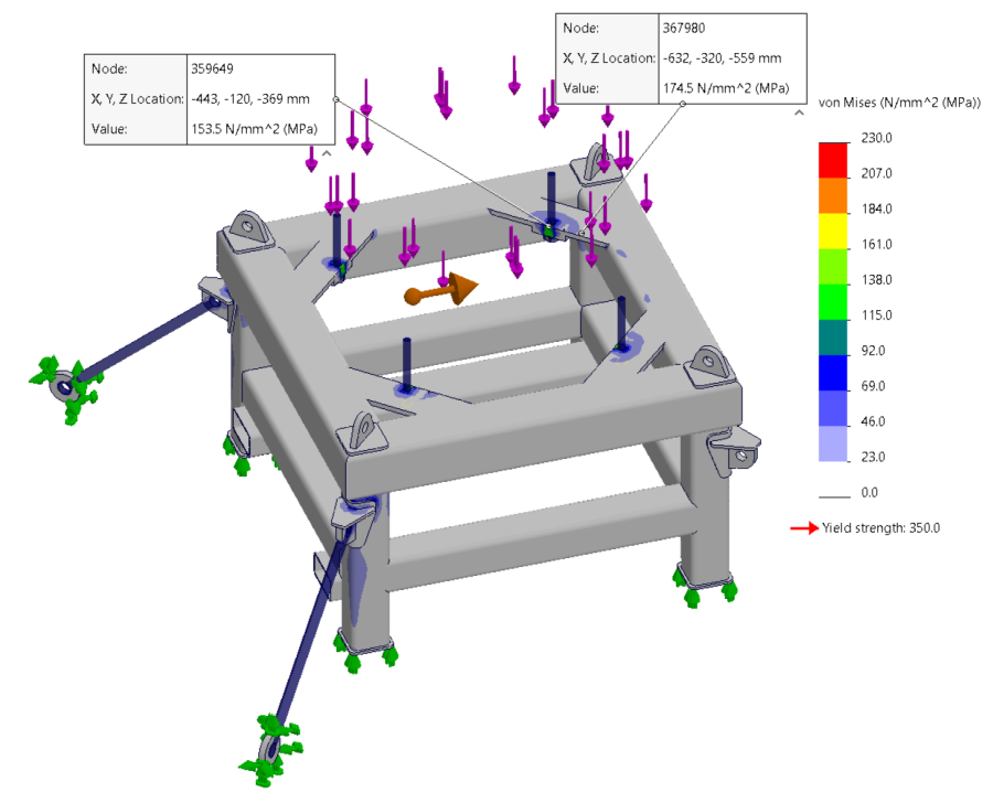
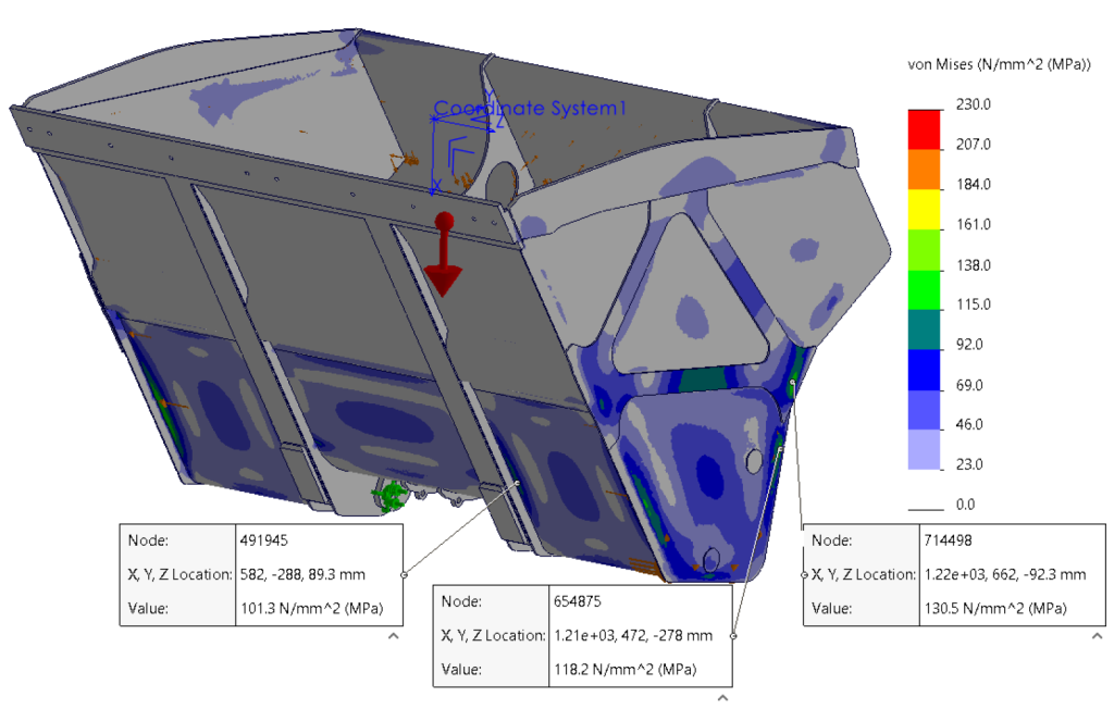
Computer assisted stress analysis streamlines the certification of equipment, because a 3D model removes the guesswork of any new designs. We can check the results straightaway and in addition make changes quickly and inexpensively. With Finite Element Analysis (FEA), we can apply several different loads such as gravity, remote force and torque. Afterwards, we can check these resultant stresses and deflections against design specifications.
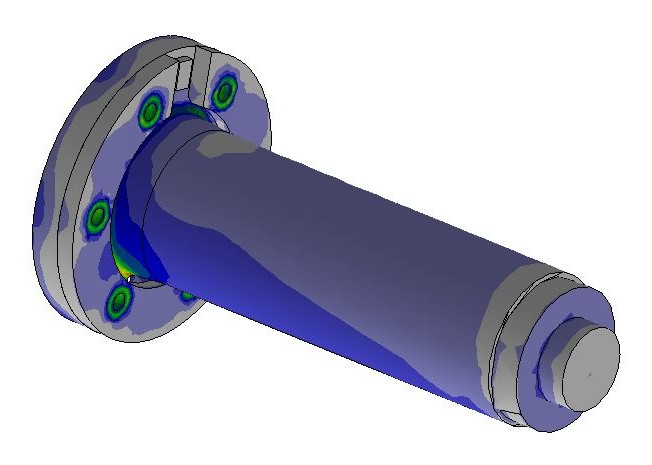
The picture below shows the stresses of a pit gearbox:
Structural Modelling
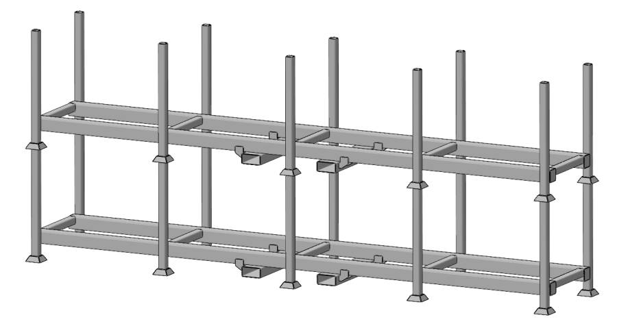
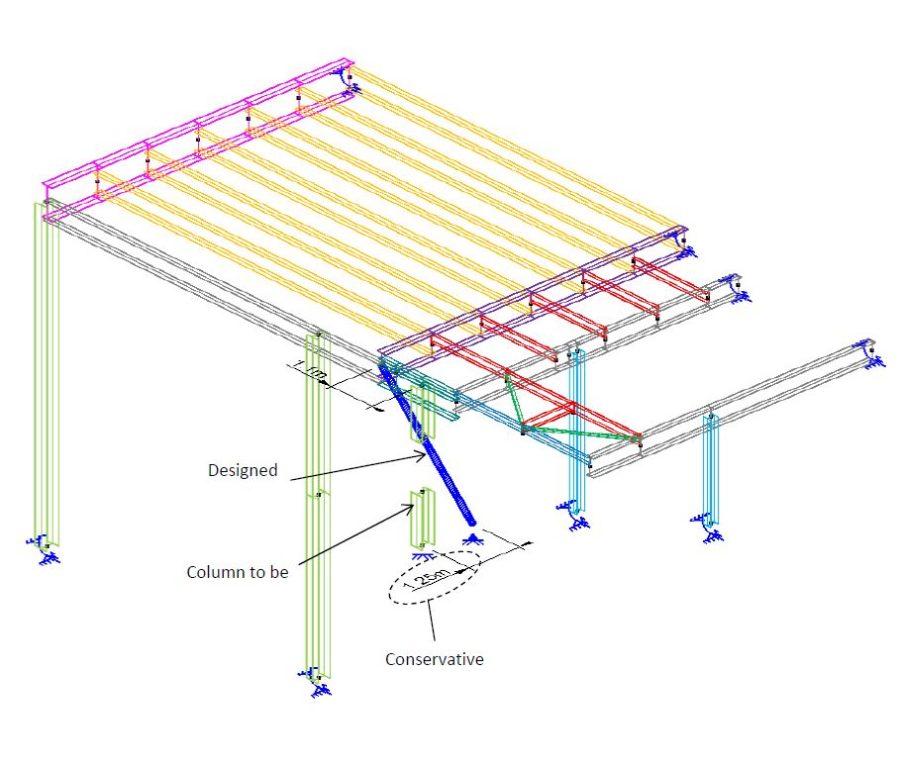
Another method of analysis is to model the structure in a program called Space Gass. This program uses beam elements to analyse more complex structures in a low-cost way. The picture below shows a Space Gass model of columns:
Physical Testing of Equipment
In some instances, computer simulation cannot be used to certify a design. Then our client needs to build a prototype and physical test the equipment, often to destruction. This approach is sometimes specified in the Australian Standard – for example for ROPS, FOPS and FUPS devices.
Please note that to certify a ROPS or FOPS structure, physical testing must be done. This is because calculations are not allowed in terms of the Australian Standard. To do this, our client would need a test rig and a sacrificial physical ROPS/FOPS structure. In most cases, it is an expensive exercise to build a test bed and destructively test a ROPS. Therefore, it only makes sense if our client is going to build large quantities of these units. Note that we would use our clients test rig – we do not have a test rig ourselves.
New / Existing Equipment Certification
Dynamic Engineering can certify both new and used equipment. For certification the following information is needed:
1) For new equipment:
- A drawing that fixes the design (dimensions, materials and welding) – if you do not have a drawing, we can create one for you
- Engineering calculations (require loads and load combinations) – we can provide these for you
2) For existing equipment:
- A drawing that fixes the design (dimensions, materials and welding). The equipment would therefore need to be measured (in some cases dismantled) – if you do not have a drawing, we can create one for you
- Engineering calculations (require loads and load combinations) – we can provide these for you
- Actual load test to confirm the design calculations and construction – we can refer you to a third party that can perform the load testing for you.
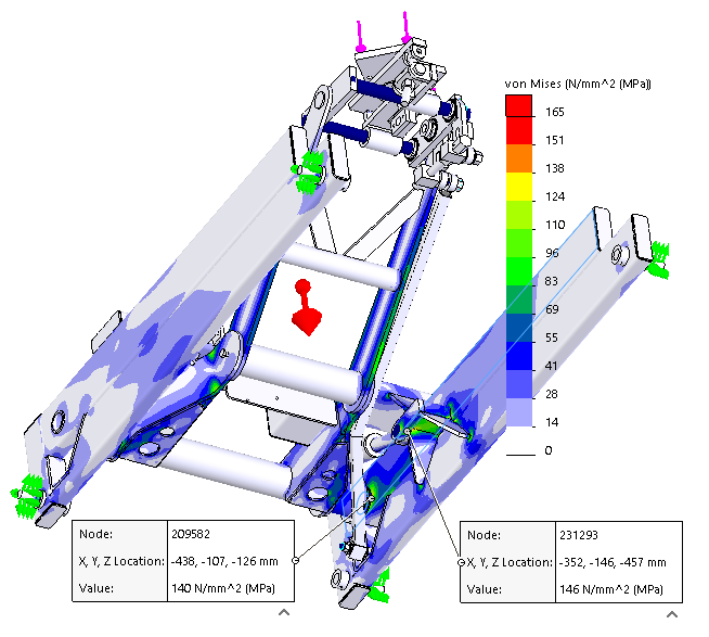
We can help with all of the above. First, we develop a 3D model of our client’s equipment and apply the loads. In this way, we can produce stress plots to prove the design or even to increase its reliability. It is fast, cost effective and saves a lot of time and money associated with breakdowns – not to mention the safety risks associated with failures.
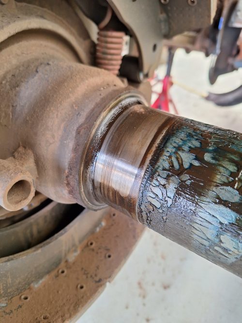
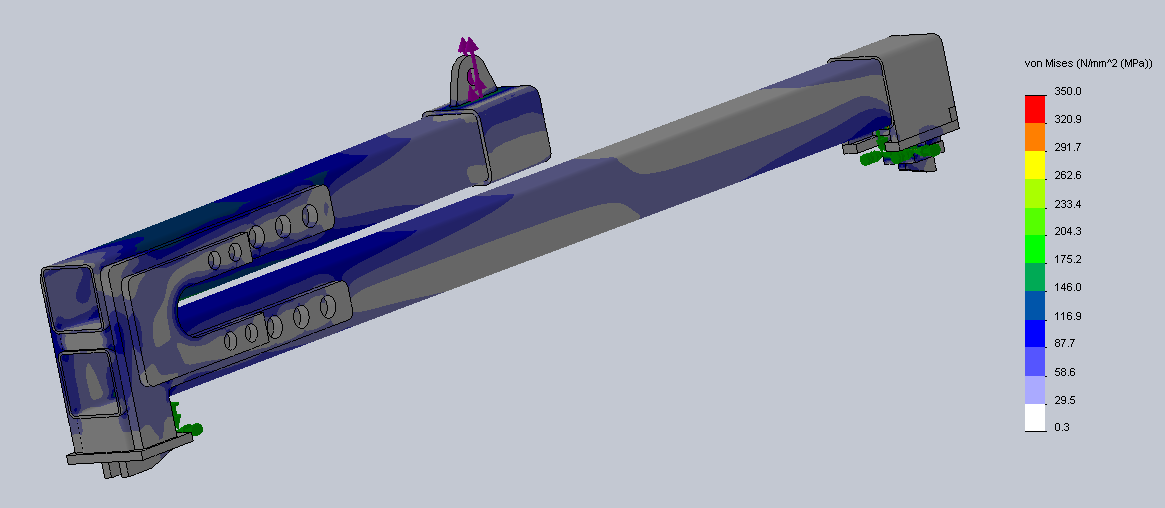
The following picture shows the stresses of a drill rig:
Independent Design Verification
Where our client has an existing design, or a design that requires independent 3rd party design verification, we can help.
In order to assist with an independent design verification, we would require the following information:
- Design Calculations
- Design Drawings (showing welding details, material standards and grades)
- Description of Use
Minimum Requirements
All designs should have a minimum level of suitable verification to satisfy the above requirements (e.g. design of safety, control and process systems).
As the potential risk associated with error in design increases, so should the level of verification. For example, pressure vessel failure is usually catastrophic and has a high risk to life consequence. So, for pressure vessels and similar high-risk designs, the depth of verification and requirements for independent verifier are higher.
Further information: Under the Mines Safety and Inspection Regulations 1995, registration of classified plant can only be completed following ‘verification by a person other than the person who prepared the design that the design complies with the Australian Standard applicable under regulation 6.33.’
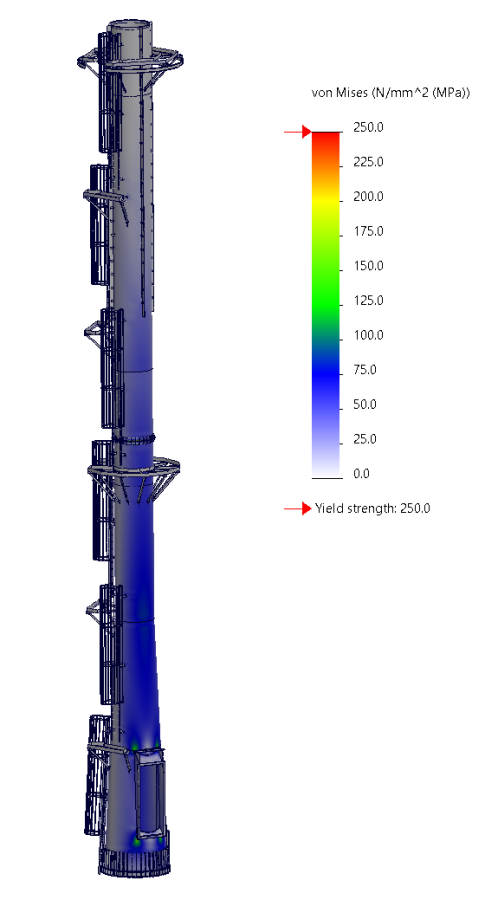
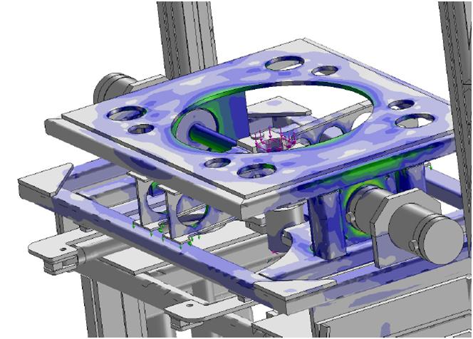
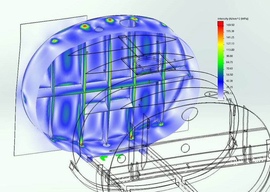
Below is an example of a design verification plot for a vacuum vessel:
Short description of FEA
The first step in computer modelling is drawing the equipment or tool in three dimensions. Secondly, we add loads and constraints. Then the CAD software meshes the model by subdividing it into smaller elements and calculates the resultant stresses and deflections for each element. Lastly, stress and deflection equations are solved for each of these elements and the results are combined to find the overall solution. We compare these results with the maximum values stated in the Standards to ensure the design complies. Finally, we present these results in a detailed report, showing the stress and deflection plots including a summary.
The picture below shows the stress analysis of a belt lifter:
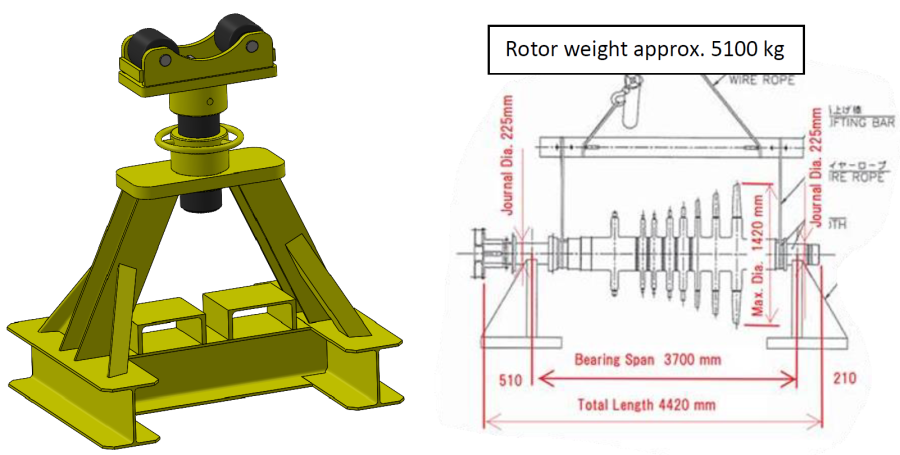
The image below shows a jacking tool:
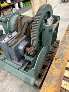
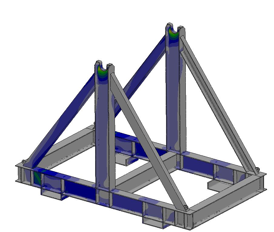
The picture below shows a reel drum frame:
Dynamic Engineering can apply FEA to several different applications, such as Machine design, Maintenance tools and Civil/Structural design.
We can help you achieve success with the right combination of Experience, Skills and Tools. Moreover, we work with our clients to find the best solution and we do this in a timely and costly manner. We can help to design, develop and install new processes or equipment, improve existing ones and reduce or eliminate downtime. As a result your goals are our goals too. How can assist you? Please contact us to discuss your specific needs. We are here to help.